Power Manager
In a CGR system all of the logic necessary to compute the different functionalities are instantiated in the substrate and the configurations are enabled by multiplexing resources in time. When a functionality is executed the rest of the design, not involved in the computation, is in an idle state. Thus, CGR systems benefits from the application of dynamic power management strategies. The part of unused resources in a CGR architecture is fixed at design-time. Thus it is possible to divide it into a set of disjointed Logic Regions (LR), composed of resources that are always active/inactive together, and reduce their power consumption by applying power saving techniques.
MDC features an automated power management technique, based on clock gating and power gating techniques, which identifies the homogenous logic regions in the design and enables/disables them at the same time, preserving the overall computing correctness.
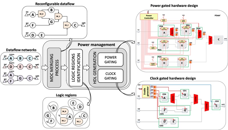
The steps of the power management flow, depicted in figure, are:
Logic regions identification: during this step MDC analyses the input dataflow models and extract from them the sets of resources that, from the functional point of view, are active/inactive together; these sets are called logic regions (LR). LRs identification allows the designer to manage the logic activation at a coarse grain level, instead of at the fine grain (single actor) one.
Power saving:
-
clock gating: clock gating management on ASIC technology is implemented by means of simple and gates, called clock gating cells, which take as input the main clock signal. When the clock gating feature is enabled, the clock gating cell output is zero, and the logic transitions associated to the clock signal (within the considered LR) do not occur anymore. On FPGA clock gating implementations requires the utilization of dedicated modules available on the board. These modules are limited in number and, in some cases, can be not enough for all the identified LRs. MDC manages this issue; if these modules are less than the number of LRs, the tool joins some LRs aiming at the minimization of the power dissipation overhead due to the sub-optimal LR.
-
power gating: power gating implementation requires a lot more additional logic (sleep transistors to switch on/off the power supply, isolation cells to avoid the transmission of spurious signals in input to the normally-on cells and state retention logic to maintain the internal state of the gated region). This logic is inserted by means of a power format file (the Silicon Integration Initiative’s Common Power Format (CPF)), which allows designers specifying power intent early in the design, relieving them from the direct modification of the RTL design. Depending on the identified LRs and their compositions, MDC write a CPF file which contains all the necessary power information. Furthermore it generates a Power Controller that drives all the enable signals necessary to the power gating logic.